Radiometrix code-hopping “K” products such as KTX2 and KRX2 can be used to implement an entry monitoring system.
Uses include private home alarm systems, site monitoring and asset management.
Real-life case study
A householder having Bed & Breakfast guests wanted to know if selected private areas of the house were being accessed. Locked doors were not an option since the private areas of concern were child bedrooms. Various burglar alarm systems were considered but none seemed to address the exact needs of the householder. A minimal impact and simple deployment were high priorities in this case.
Requirements
Solution overview
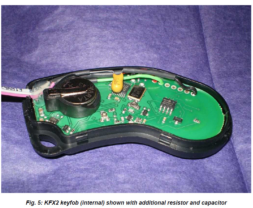
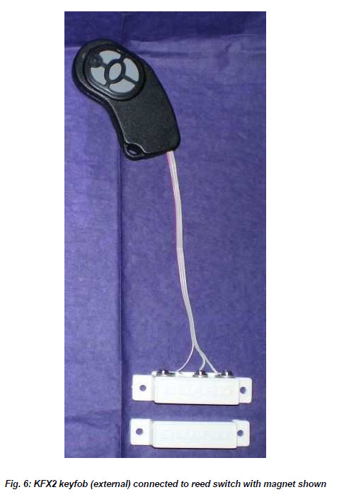
For convenience in this particular example, two KFX2 (Keyfob) code-hopping transmitters were adapted for use with changeover reed switches (one per door). The KTX2 module is essentially the same as a KFX2 but without plastic case, buttons and batteries. A specific implementation could use KTX2 + battery + reed switch all in one small case.
The remote indicator and alarm device used a KDEC-44, which is KDEC software implemented on a slightly modified CTR44 demo board (This part is available as KDEC-44-000). Again, this was selected for convenience – a KDEC board could have been used or (if relay outputs were not required) a KRX2.
The KDEC software itself was also slightly modified to provide true latched outputs (rather than a toggle on/off). Up to four rooms could be monitored using a KDEC-44 board. To reset the outputs an external reset input was added: this was wired to a push-button. This variation in KDEC software (and others) is available on request when ordering your KDEC, or KRX2.
Door sensor - transmitter unit
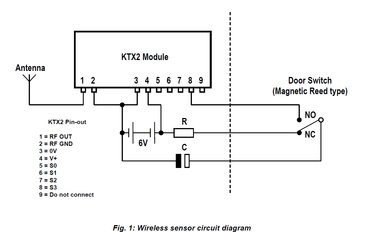
As can be seen from the diagram above, the implementation of a wireless sensor for door monitoring using KTX2 is very simple: The addition of a single resistor, capacitor and low-cost magnetic reed switch is all that is required. When the door is closed C charges from the battery through R. When the door opens C discharges into one or several of the KTX input pins causing a transmission to occur. In the example shown function code 8 (binary 1000) would be sent. One KTX2 input per door was used but up to 15 doors could be monitored using the combinations that 4 inputs offer. If using a KRX2 at the remote monitoring station, the addition of a 4 - 16 line decoder IC could form part of such a system.
Suggested values and types for R & C:
R = 1MΩ metal film
C = 10µF Tantalum 25V
The slow charging of capacitor C ensures a lack of “nuisance” alarms and prolongs battery life. It takes C*R seconds (worst case) to provide enough charge to cause a transmission upon re-opening the door but experimentation shows that around half this time can be sufficient. When C is fully charged opening the door causes a transmission of approximately 3 seconds duration. Many individual (repeated) messages are sent during this period, mitigating interference. C could be changed to 4.7µF and R increased to 2.2MΩ to increase battery life (at the expense of transmission duration). If more than one input were to be connected the transmission time would be reduced. For example, if all inputs were connected (to send function code 15, binary 1111) the transmission duration would be one quarter of a single input transmission.
Note that the capacitor does not provide the module power supply during transmission, it simply discharges through the input pin(s). Tantalum or ceramic types should be used. Electrolytic capacitors are not suitable because of their relatively high leakage current.
The 6V battery could be two lithium coin cells (as used in the KFX2 keyfob) or a photo-camera alkaline battery type 4LR44 or PX28A, which is equivalent in physical size to a ½AA cell. Current drawn from the battery during transmission is approximately 8mA (for KTX2 – 2mW standard version). When not transmitting the current drawn is less than 1µA.
Remote indicator and alarm - receiver unit
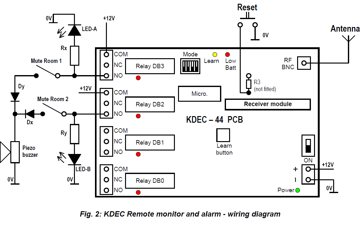
At the remote monitoring / alarm station the KDEC board is wired to light LEDs (one per monitored room: two room example is shown in Fig. 2). A piezoelectric alarm sounder is connected via mute switches and a diode logic OR circuit formed by Dx+Dy. Finally, a push-button switch provides the Reset input because once a relay has been energised it is latched by the KDEC. The MODE DIP switches are all set to “ON”, to enable Latched mode for all relay outputs. The door sensor transmitters are simply learned into the memory of the decoder: press the Learn button and open a door. The transmitter identification is stored in the memory and is retained when power is removed.
One point to bear in mind is that if the remote monitor is un-powered and a door is opened more than 14 times during this period then the door must be opened twice when the unit is re-powered in order to re-synchronise the decoder. This is a security feature of code-hopping decoders more useful in control situations. The remote monitor should therefore remain powered, or when re-powered the system should be checked and if necessary re-synchronised to the transmitters as described above.
The assembly can be fitted into a plastic enclosure and powered from an inexpensive 12V wall adaptor. As the relays are capable of switching 240VAC at several amps there are many possibilities for switching, including external security lighting or powerful alarm sounders.
Expected range
Predicting the range obtainable in any given situation is notoriously difficult since there are many factors involved. The main ones to consider are as follows:
Assuming the use of ¼-wave whip antennas on both transmitter (@ 2mW) and receiver, the following ranges may be used as a rough guide only:
Cluttered/obstructed environment, e.g. inside a building : 50-75m Open, relatively unobstructed environment : 200-300m
It must be stressed, however, that range could be much greater or much less than these figures. Range tests should always be performed before assuming that a particular range can be achieved in any given application.
Antenna considerations and options
The choice and positioning of transmitter and receiver antennas is of the utmost importance and is the single most significant factor in determining system range. The following notes are intended to assist the user in choosing the most effective arrangement for a given application.
Nearby conducting objects such as a PCB or battery can cause detuning or screening of the antenna which severely reduces efficiency. Ideally the antenna should stick out from the top of the product and be entirely in the clear, however this is often not desirable for practical or ergonomic reasons and a compromise may need to be reached. If an internal antenna must be used, try to keep it away from other metal components and pay particular attention to the “hot” end (i.e. the far end), as this is generally the most susceptible to detuning. The space around the antenna is as important as the antenna itself.
To minimise adverse effects, situate the antenna and module as far as possible from any such circuitry and keep PCB track lengths to the minimum possible. A ground plane can be highly effective in cutting radiated interference and its use is strongly recommended.
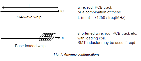
Two examples of antenna are given here for use at 433MHz in this application:
Whip (¼-wave). This consists simply of a piece of wire or rod connected to the module at one end. The lengths given below are from module pin to antenna tip including any interconnecting wire or tracking (but not including any 50 coax or microstrip connection). This antenna is simple, cheap, easy to set up and performs well. It is especially effective when used with a ground plane, which in practice is often provided by the main PCB or by a metal case.
Base-loaded whip. In applications where space is at a premium a shortened whip may be used, tuned by means of a coil inserted at the base. This coil may be air-wound for maximum efficiency, or a small SMT inductor can be used. The value must be empirically chosen to tune the particular length of whip for best results “in situ”, making this antenna more difficult to set up. Radiated power will generally be slightly less than that obtained from a ¼-wave whip.
Radiometrix can supply read-made antennas for use with the KDEC and KTX modules – see our website for more details. In the practical example given in this application note a BNC terminated ¼ wave whip antenna was used at the remote monitoring station.
Type Approval requirements: Europe
The equipment described will comply with the requirements of the R&TTE Directive (including standards EN 300 220-3 and EN 301 489-3) when used in the manner detailed in this application note.
Module mounting considerations
Good RF layout practice should be observed for best results. In particular, any ground return required by the antenna or feed should be connected directly to the RF GND pins at the antenna end of the KTX2 module, and not to the 0V pin which is intended as a DC connection. All connecting tracks should be kept as short as possible to avoid any problems with stray RF pickup.
If the connection between module and antenna does not form part of the antenna itself, it should be made using 50 microstrip line or coax or a combination of both. It is desirable (but not essential) to fill all unused PCB area around the module with ground plane.
Variants and ordering information
The following UHF equipment is available as standard:
| Part number | RF power (typ.) | Frequency |
| KTX2-433 | +3dBm | 433.92MHz |
| KFX2-433 | Integral antenna | 433.92MHz |
| KDEC-433-000 | - | 433.92MHz |
| KRX2-433 | - | 433.92MHz |
| KDEC-44-000 (board only 1) | - | - |
| KRX416 (decoder I.C. 1) | - | - |
1 A suitable receiver module must be used in conjunction with these items – e.g. RX2G-433-15.
For greater range, more power and/or a lower RF frequency could be used. Remember that at VHF the antenna will be physically larger. 173MHz is a UK-specific frequency band for Short Range Devices.
| Part number | RF power (typ.) | Frequency |
| KTX2-433-10 | +10dBm | 433.92MHz |
| KTX1-173 | +10dBm | 173.25MHz |
| KDEC-173-000 | - | 173.25MHz |
| KDEC-44-000 (board only 2) | - | - |
| KRX416 (decoder I.C. 2) | - | - |
2 A suitable receiver module must be used in conjunction with these items – e.g. NRX1-173.250-10.
Non-standard versions can be supplied to individual customer requirements. Minimum order quantities apply. Please consult the Sales department for further information.
Conclusion
This application note has illustrated by way of an example how easy it is to use Radiometrix K series modules and products to provide a wireless monitoring and alarm solution. In the example shown a domestic door monitoring system was implemented but general and security applications for Radiometrix low-power RF code-hopping systems are everywhere.
Radiometrix Ltd Hartcran House 231 Kenton Lane Harrow, Middlesex HA3 8RP
England
Tel: +44 (0) 20 8909 9595
Fax: +44 (0) 20 8909 2233
sales@radiometrix.com www.radiometrix.com
Copyright notice
This product data sheet is the original work and copyrighted property of Radiometrix Ltd. Reproduction in whole or in part must give clear acknowledgement to the copyright owner.
Limitation of liability
The information furnished by Radiometrix Ltd is believed to be accurate and reliable. Radiometrix Ltd reserves the right to make changes or improvements in the design, specification or manufacture of its subassembly products without notice. Radiometrix Ltd does not assume any liability arising from the application or use of any product or circuit described herein, nor for any infringements of patents or other rights of third parties which may result from the use of its products. This data sheet neither states nor implies warranty of any kind, including fitness for any particular application. These radio devices may be subject to radio interference and may not function as intended if interference is present. We do NOT recommend their use for life critical applications.
The Intrastat commodity code for all our modules is: 8542 6000
R&TTE Directive
After 7 April 2001 the manufacturer can only place finished product on the market under the provisions of the R&TTE Directive. Equipment within the scope of the R&TTE Directive may demonstrate compliance to the essential requirements specified in Article 3 of the Directive, as appropriate to the particular equipment.
Further details are available on The Office of Communications (Ofcom) web site:
http://www.ofcom.org.uk/radiocomms/ifi/
Information Requests Ofcom
Riverside House
2a Southwark Bridge Road London SE1 9HA
Tel: +44 (0)845 456 3000 or 020 7981 3040
Fax: +44 (0)20 7783 4033
information.requests@ofcom.org.uk
European Radiocommunications Office (ERO)
Peblingehus Nansensgade 19
DK 1366 Copenhagen
Tel. +45 33896300
Fax +45 33896330