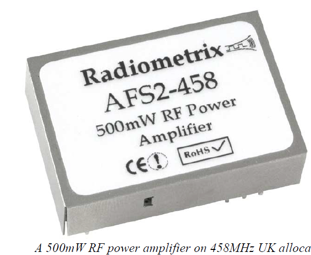
As perceived by the general engineering community, ISM band radios are very innocuous things. Robust little modules drawing a few tens of milliamps from the supply, to radiate a few milliwatts from a generally non-critical aerial. In most cases, this is true, but like most rules there are exceptions: the wide category of ‘low power radios’ actually includes devices which emit up to half a watt of RF energy. These include units in the UK’s 458MHz ‘industrial telemetry’ allocation, the European 869.4 - 869.69MHz sub-band, and various other country specific bands (for example: the Czech Republic permits 500mW on certain 148, 156 and 448MHz frequencies)
Such units are most frequently used in long range or high reliability applications (such as radio modems and industrial control apparatus) but still fall under the unlicensed band regulations EN300-220. Much higher power radios are used in licensed allocations (PMR bands, long range MPT1411 telemetry) but these are outside our scope.
Half a watt of RF energy is quite a lot of power to be dealing with. To give some sense of scale: across 50ohms this corresponds to 5 volts rms (or 14v peak to peak). By comparison 1mW is barely 220mV rms.
For the engineer planning to use such devices there is a whole new minefield of considerations:
Mismatch: In the ideal world every aerial load presented to the transmitter would look like a perfect 50 ohm resistor, and then all the output power would be radiated usefully away. But the real world isn’t really like that.
Aerial mismatch, due to poor tuning, incorrect specification or improper mounting (insufficient groundplane, or too much adjacent metalwork) causes some of the power to be dissipated elsewhere, reflected back into the transmitter to be dissipated as heat, or radiated from the feeder coax.
When a simple, 10mW, ISM module is being used then only a reduction in link range is likely to be seen. At 500mW things are different. That energy that isn’t being radiated out of the aerial goes somewhere. Some transmitters can suffer damage or faulty operation when driving a badly terminated load, from thermal overload, output device failure, or sometimes instability (Although other units are specified to survive such abuse: check your supplier’s datasheets).
Susceptibility: The whole point of a transmitter is that it radiates RF energy. When this energy turns up in unwanted places, trouble follows. Any length of conductor is a potential receiving ‘aerial’ (all the more so if the conductor is a multiple of 1/4 wavelength), including all the internal wiring and pcb tracking of your design. And that results in induced RF voltages in places they should not be.
Every PN junction acts as a rectifier for these interfering signals. In analogue circuitry this causes changes in bias, and voltage errors. In digital sections spurious logic triggering, faulty program execution and even resets can result. When the RF signal itself switches on and off, then there is a further problem: an audio frequency interferer (at the switching rate) also appears, as the junctions act as AM demodulators. (This is the ‘bleeping and howling’ heard when an active GSM phone is placed too close to your audio system)
As well as producing unwanted voltages, the non-linear nature of a semiconductor junction when driven with a large RF voltage gives rise to the generation of harmonics of the original frequency, which may then be re-radiated from the circuitry. In this way, a system can fail type approval harmonic and spurious emission limits, even when the transmitter is well within specification if tested separately.
Recirculation: Even when the transmitter appears to be operating normally, with a stable output spectrum and expected supply current drawn, there is still a possible failure mode in hiding: If excessive RF energy is allowed to leak back into the transmitter itself then a phenomena known as ‘recirculation’ manifests as unpredictable (and sometimes bizarre) distortion in the baseband signal. This distortion (as seen on the receiver AF output) is frequently worse during transmitter switch-on.
Multichannel, synthesised designs suffer far more readily from this problem. (What is happening is that the RF energy is leaking back into transmitter’s local oscillator, and upsetting the frequency synthesizer loop. In extreme cases the disturbance is so severe that the unit loses phase lock and resets, giving rise to a low frequency power-up / shut-down oscillation known as ‘motor-boating’).
It is all too easy to blame non-existent receiver defects, or external interferers, for this problem, especially as the transmitter is unlikely to exhibit the effect when being bench-tested into a dummy load. The amount of RF leakage necessary to cause a recirculation problem is far less than that necessary for ‘real’ RF instability
Power supplies: Half-watt class radios draw considerably more current that their smaller, lower powered fellows. Few designs exceed 50% overall efficiency, and a typical module is likely to draw 300-500mA from a 5v supply, with even higher peak currents as the units ‘keys-on’. This can cause a significant battery voltage ‘droop’, or cause regulator fold-back.
So what should you do ?
Beyond the usual good practice when using a wireless module, there are a few extra precautions to be taken at higher power levels:
• Use a good aerial: Make sure the aerial chosen is properly set up for the frequency of operation, and that sufficient groundplane (required by monopoles and whips) is present. Ensure the aerial is mounted away from metal structures (which will de-tune it), and as high up as possible. Use a VSWR meter to optimise the aerial tuning, if necessary. Avoid running other cables near the
aerial.
• Use adequate shielding: Mount your circuitry (and the transmitter) inside a metal, shielded enclosure if at all possible. Use a bulkhead mounted RF connector, to ensure the braid of the aerial cable is properly earthen to the enclosure wall. Use good RFI filtering on all wiring at the point of exit from the housing (feed through capacitors are effective, although somewhat old fashioned looking. Filtered connectors, containing ferrite blocks or LC filter circuits, are especially useful)
• Remember Power, and heat: Provide an adequately rated power supply for your transmitter, ideally separate from the analogue and logic rails in your design. The module will dissipate 1-3
watts of heat (at least) when in operation, so provide good ventilation, any necessary heat sinking, and limit transmit duty cycle.
• Test for known problems: Monitor the analogue baseband output of your receiver, or use a separate monitor receiver or ‘scanner’ and look for unexpected distortion in the transmitter’s modulation. Test into a dummy load and into the chosen aerial, and look for differences.
• Be careful: Half a watt doesn’t sound like a great deal, but the field near to the aerial can interfere with the operation of unshielded electronics, and can block other receivers. Locate your transmitter, and it’s aerial, carefully.
• And, as always, test everything: A 500mW link should have a range in kilometres: if it doesn’t, then something is wrong.
By Myk Dormer for Radiometrix Ltd
First published in Electronics World magazine.