Low power ISM band modules are well established in a wide variety of short range, high and low data-rate applications. Often referred to as ‘SRDs’ (‘Short Range Devices’), it is commonly assumed that these solutions are usable only over very limited distances.
Well, it all depends on what you mean by ‘short range’. Simple, wideband ISM implementations rarely exceed 100m range. Popular 2.4GHz network devices don’t even approach that figure. And rarely need to. But there are a sub-set of low power radio tasks where longer ranges are desirable.
Alarms and high value asset tagging systems can need to cover extensive industrial sites, agricultural monitoring and control devices frequently need ranges exceeding a kilometre, and maritime telemetry calls for even longer ranges. While there are existing infrastructure based wireless systems (such as GPRS, or even ARGOS), or high power licensed band radios, that guarantee far longer range by design, there is a lot that can be achieved with very simple ISM modules, provided a few simple considerations are taken into account.
So what defines range ? The range expected of a radio link is the point at which the path loss between the aerials equals rx_sensitivity - tx_power (the ‘link budget’). A margin for fading and uncertainty, of usually 10 - 20dB, is normally added to the path loss.
From the path loss model (see footnote) we can see that the path loss is proportional to 10 x log(1/d^4), where ‘d’ is the range in meters.
As a rough rule, this suggests that to double the range, it is necessary to improve the link by about 12dB.
A lower data rate will also allow the use of narrow band radios, with higher sensitivity and better rejection performance than simple wideband modules (refer to note
2). To make best use of very low data rates, special techniques must be employed, processing the AF output before squaring, or in some cases the IF signals. Some implementations use DSP techniques to achieve sub-10Hz effective band widths, and sensitivities better than -150dBm.
Path loss increases with frequency, proportional to -10 x log(1/f^2). Which means that, (assuming the same aerial gain, transmit power, and receiver sensitivity) a 173MHz VHF link will see 14dB lower path loss than an 869MHz one. In other words, a 10mW, 173MHz link will have similar range to an 80mW 458MHz one, a 250mW 869MHz one, or a (hypothetical) 2 watt system at 2.4GHz!
But lower frequencies require larger aerials for a given aerial gain performance, which can be an issue in the mechanical design of the product. (An 869MHz whip aerial is 9cm long. The same 1/4 wave antenna at 173MHz is 43cm).
A good rundown of the available UK frequency allocations can be found here: http://www.ofcom.org.uk/static/archive/ra/publication/ra_info/ra114.htm http://www.ofcom.org.uk/static/archive/ra/publication/ra_info/ra365.htm
For long range links, plan to use a good quality helical (not a compressed ‘stub’ design) or a quarter wave whip as a minimum. If space (and cost) constraints permit, then a true dipole or a 5/8 wavelength design will offer superior performance.
But pay especial attention to radiated power limits in the chosen band, which will prohibit the use of an antenna with more than unity (0dBi) gain at the transmitter. The receiver antenna can, however, have as high a gain as circumstances permit. On fixed links even highly directional ‘Yagi’ arrays can be used, with gains sometimes exceeding 20dBi.
Mounting the aerials 2m above ground level will improve the path loss by 12dB, and double the expected range. 4m elevation of both (the height of a first floor window ledge) should quadruple the range.
Go out and try it.
Note 1: Referring to the Egli irregular terrain path loss model, expressed in dB terms:
path gain (dB) = 32.4 + 10 x log(1/d^4) + 10 x log(1/f^2) + 10 x log ((Hr x Ht)^2) + Gt + Gr F = frequency in MHz d = distance in meters
Gt, Gr = transmit and receive antenna gain (dBi)
Ht, Hr =height above ground of transmit and receive aerials
Note 2. Practical data rate testing:
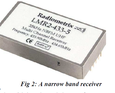
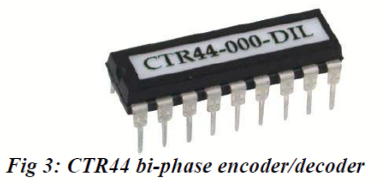
Using a CTR44 biphase coder/decoder pair, and a -120dBm (for 12dB sinad) narrowband receiver (a Radiometrix LMR2-433-5).
Reliable (sub-1% data error) signalling at 4kbps -116dBm 2kbps -118dBm
1kbps -120dBm
500bps -122dBm
250bps -124dBm * 125bps -126dBm * 62bps -127dBm *
* Without reducing the post-detection AF bandwidth, no improvement beyond -122dBm is seen. The 250, 125 and 60 bps figures are achieved with the reduction in filter bandwidth to 300, 150 and 75Hz respectively. At data rates below 50 bps, the receiver’s data extractor (an ‘average and compare’ circuit) is no longer functional.
Simple communications theory predicts a 3dB improvment in S/N (and hence signalling sensitivity) with each halving of bandwidth. This is not seen here, as the FM demodulator and the data squaring comparator introduce non-linear transfer functions into the signal path
See also Application note 003: Long range low speed telemetry http://www.radiometrix.co.uk/apps/apnt003.htm
for a description of a practical 30 bps example.
By Myk Dormer for Radiometrix Ltd
First published in Electronics World magazine.